Custom FPV Drone
A ground-up quadcopter build that required component compatibility, precise soldering, signal configuration, failsafe behavior, systematic troubleshooting, and staged flight validation.
Problem and motivation
The goal was to build a complete FPV aircraft from individual components rather than start with a ready-to-fly system. That meant treating the drone as a connected electrical and control system: every power rating, signal protocol, connector, firmware setting, and physical mounting decision had to work with the others.
The project created a practical way to learn electronics, soldering, configuration, and troubleshooting while producing a system that could be validated in real flight.
Goals and constraints
- Select a frame, motors, electronic speed controllers, flight controller, receiver, video system, and battery that could operate safely together.
- Fit the complete electrical system into a compact carbon frame while protecting signal wiring and high-current paths.
- Configure receiver channels, arming behavior, motor direction, flight modes, and failsafe response before flight.
- Diagnose power, communication, and configuration faults without risking props, electronics, or nearby people.
System architecture
The receiver sends control data to the flight controller over SBUS. Betaflight interprets pilot input and sensor data, then commands the electronic speed controllers. A separate camera and video-transmitter path provides the live first-person view.
Implementation
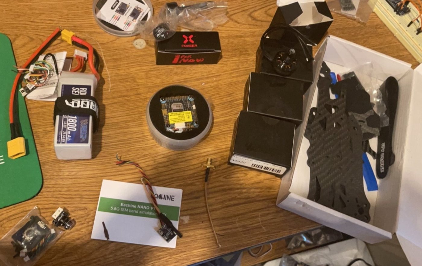
- Compared electrical ratings, signal protocols, physical dimensions, and connector requirements before finalizing the component set.
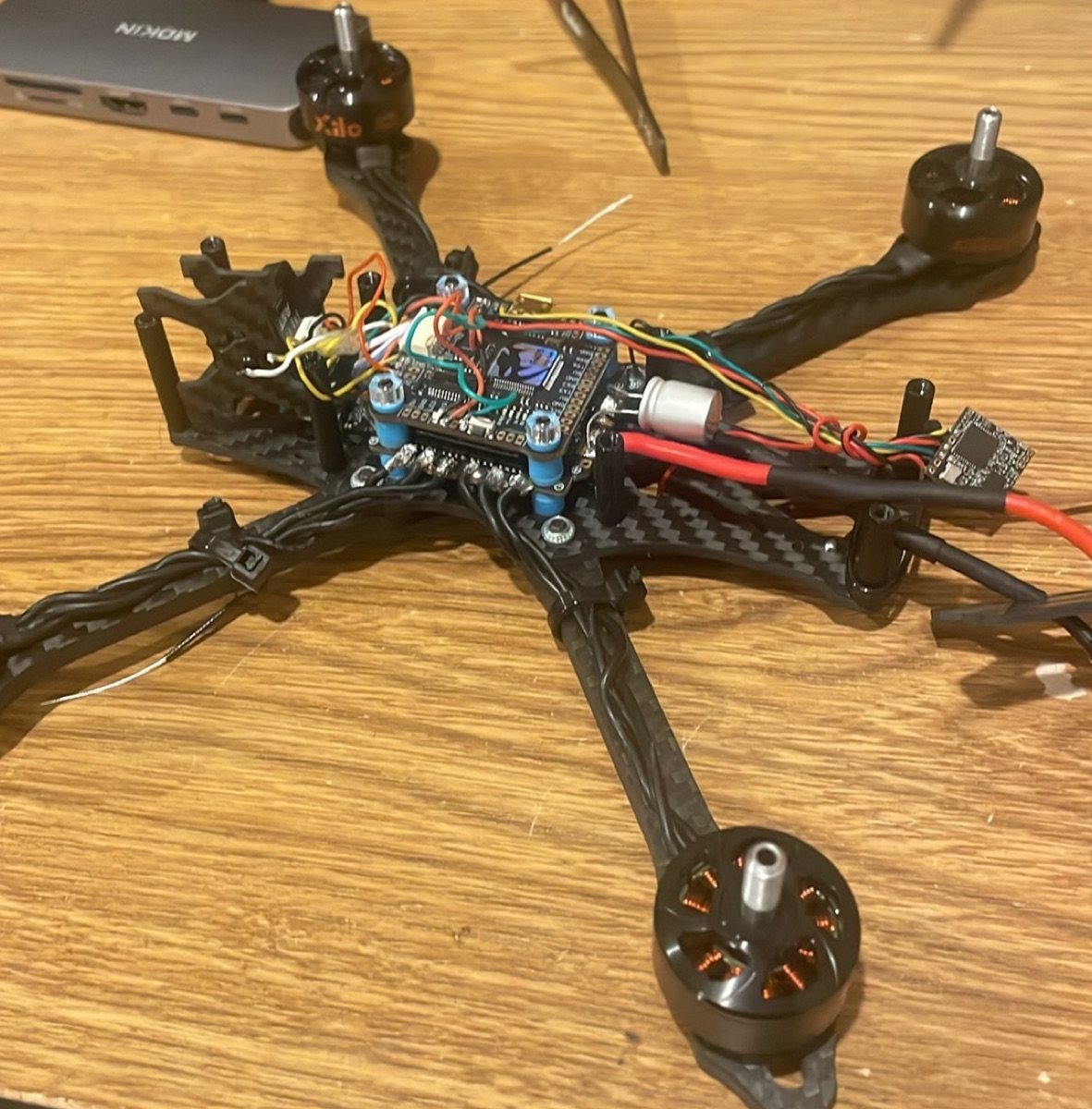
- Mounted the stack and motors, routed wiring, and soldered power, motor, receiver, and video connections.
- Configured Betaflight for receiver input, channel mapping, motor orientation, arming, flight modes, and failsafe behavior.
- Verified SBUS controls and checked that stick movement matched the expected software channels before enabling motors.
- Organized and secured wiring to reduce strain and keep conductors away from moving parts.
Major challenges and solutions
Compatibility across several subsystems. A component can be electrically suitable but still use the wrong signal protocol, mounting pattern, or connector. I compared requirements at the system level and treated every interface as something that needed verification.
Distinguishing wiring faults from configuration faults. When a control or motor did not behave as expected, I worked through the path in order: power, physical connection, receiver signal, software configuration, and output.
Testing safely. Configuration checks were completed with propellers removed. Motors, receiver input, arming, and failsafe behavior were validated independently before a controlled outdoor flight.
Testing and validation
- Inspected solder joints, wire routing, and polarity before applying power.
- Confirmed receiver channel movement and failsafe response in Betaflight.
- Tested each motor independently with propellers removed and corrected direction where needed.
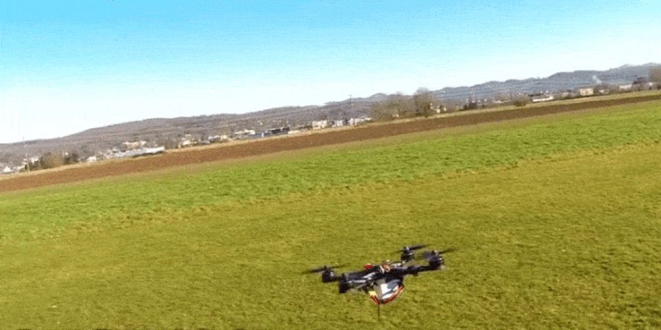
- Performed short, controlled outdoor flights before expanding the operating envelope.
Result
The finished quadcopter powered up, accepted the configured radio controls, transmitted a live FPV video signal, and completed controlled outdoor flight testing.
Lessons learned
- Systems integration problems are easiest to solve when each interface is tested separately.
- Good wire routing and mechanical strain relief are part of electrical reliability.
- A repeatable preflight checklist reduces risk and makes troubleshooting faster.
- Configuration software is most useful when paired with a clear physical model of the hardware.